Other connections are shown in the circuit diagram. This circuit is tested on the breadboard as a given diagram. Texas instruments cd40106b sponsored links. Here, we have used the complementary pair comprising common gate (pin 10), individual drains (pins 9 and 11) and common output (pin 12) as a very high input micropower linear amplifier capable of amplifying the. The working principal of the circuit doorbell is simple.
Doorbell Help - Raspberry Pi Forums from electrical-systems-lighting.knoji.com Some or all of the cameras do not appear on my dvr screen. A wide variety of doorbell circuit diagram options are available to there are 8 suppliers who sells doorbell circuit diagram on alibaba.com, mainly located in asia. Working of the circuit and code. .related searches for circuit diagram of electronic doorbell doorbell circuit diagramsimple doorbell circuit diagramelectronic doorbell chimes circuitdoorbell circuit schematicdoorbell schematic diagramelectronic doorbell systemdoorbell circuit imagesimple doorbell circuit. It can be used as doorbell. There are two switches s2 and s3 for front and rear door respectively. Video doorbells are getting smarter, and our integrated circuits and reference designs will help you differentiate your next design. The working principal of the circuit doorbell is simple.
Other connections are shown in the circuit diagram.
Other connections are shown in the circuit diagram. It is intended for applications such as toys, door bells, music boxes, melody clock/timers and telephones. Among electronics students and hobbyists, doorbell circuit project is quite popular. Standard electrical/electronic household doorbells have two parts, some sort of activation device such as the common push button at the door, the second if in a block of flats the circuits can be far more complex and power supply is built in to the system. The top countries of supplier is china, from which. The main component for the doorbell circuit for the deaf people is the cmos 4001 integrated circuit, which has four two input nor gates. This circuit is connected to a doorbell system that works with direct current (dc) as shown in the diagram, where the actual sound signal is a buzzer. The working principal of the circuit doorbell is simple. A simple wireless doorbell circuit is discussed in the following post which can be constructed at home. The main objective of the doorbell circuit is to convert electrical signals (input) into audio signals (output) with a single press of a switch. Wired doorbells are simple electrical systems. They are becoming obsolete because of these reasons and are gradually being replace by advanced wireless a push button is connected between ad8 (pin 10) and ground. Circuit, diagram, ding, doorbell, greet.
Integrated circuit doorbell forwarded to: Additionally, the circuit includes a cmos 4026 counter display driver ic to count your visitors. I think it is better to give some more detailed explanation about this circuit. Texas instruments cd40106b sponsored links. The top countries of supplier is china, from which.
How To Install A Doorbell From Scratch | MyCoffeepot.Org from i.pinimg.com Translated to malayalam by user:abhijith sheheer. If we install this automatic doorbell using object detection circuit, the circuit will automatically sense the presence of the person and it rings the doorbell. A simple wireless doorbell circuit is discussed in the following post which can be constructed at home. The main objective of the doorbell circuit is to convert electrical signals (input) into audio signals (output) with a single press of a switch. Other connections are shown in the circuit diagram. The presented circuit of doorbell in this site is employs a direct couple complementary amplifier and two regenerative latches. Simple doorbell circuit diagram and schematic using um 66 ic, which is a music sound generator. The main component for the doorbell circuit for the deaf people is the cmos 4001 integrated circuit, which has four two input nor gates.
Integrated circuit doorbell forwarded to:
Musical doorbell circuit diagram this musical doorbell circuit uses um3481 a series ic. .related searches for circuit diagram of electronic doorbell doorbell circuit diagramsimple doorbell circuit diagramelectronic doorbell chimes circuitdoorbell circuit schematicdoorbell schematic diagramelectronic doorbell systemdoorbell circuit imagesimple doorbell circuit. Simple led circuits led projects schematic circuit diagram. Among electronics students and hobbyists, doorbell circuit project is quite popular. The um3481a is designed to play the melody according to the previously programmed information. This tutorial covers a circuit diagram for door bell using 555 timer ics. Video doorbells are getting smarter, and our integrated circuits and reference designs will help you differentiate your next design. This is an easy to make electronic doorbell circuit. In this video we show you how to wire a doorbell. Integrated circuit doorbell forwarded to: Electrician's diagrams show the cables and wiring connections of a typical circuit in your home. Doorbells are usual signaling devices used to alert the person inside the building to open the door as someone has arrived. Working of the circuit and code.
I have another circuit for automatic door bell with object detection. This doorbell wiring diagram will work for all doorbells including smart doorbells like the ring doorbell. 806 doorbell circuit diagram products are offered for sale by suppliers on alibaba.com. I think it is better to give some more detailed explanation about this circuit. If we install this automatic doorbell using object detection circuit, the circuit will automatically sense the presence of the person and it rings the doorbell.
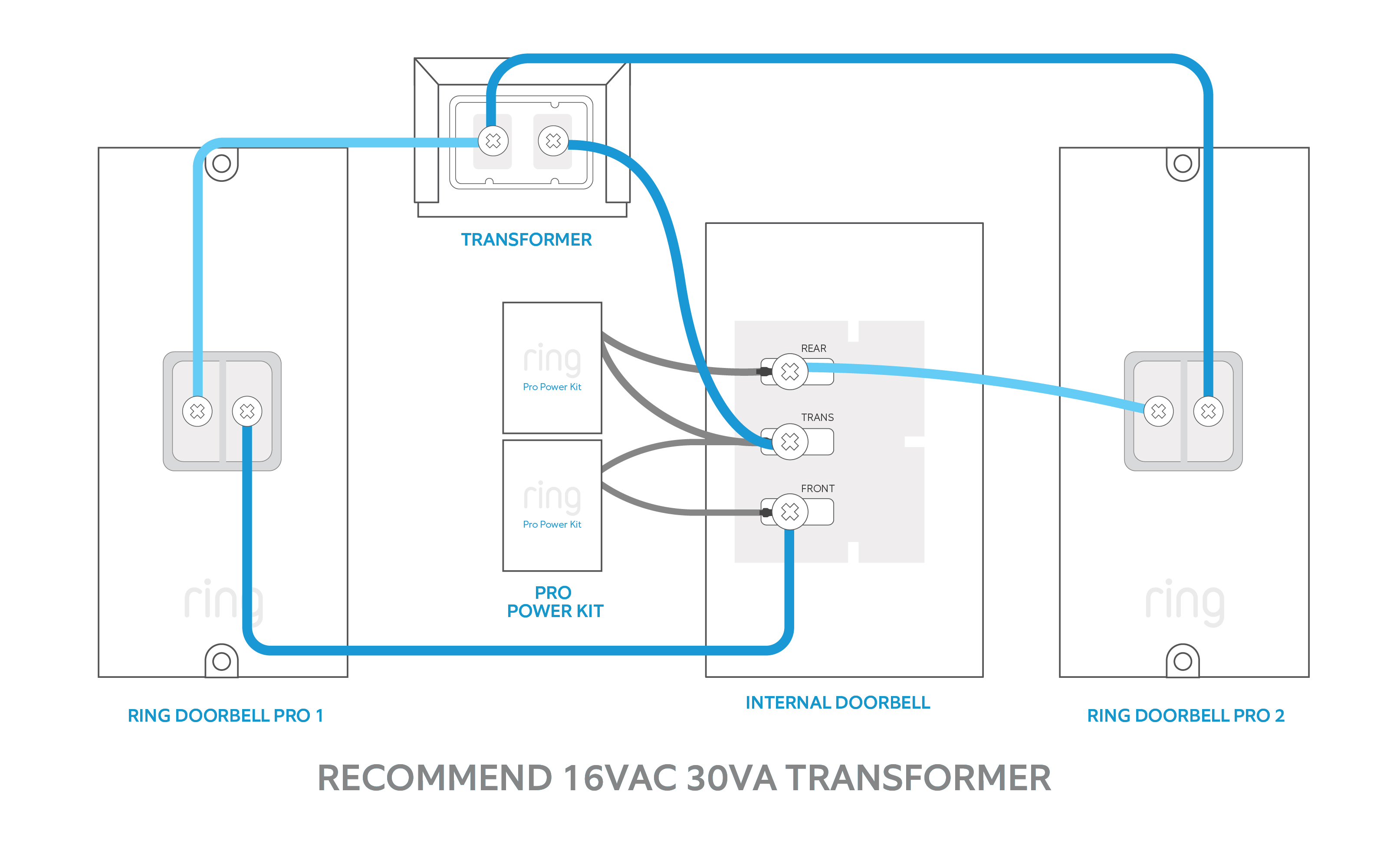
Wiring Diagrams for Ring Video Doorbell Pro Setup - Ring Help from support.ring.com Traditional doorbells are wired devices and are usually fixed at one place. Advanced features such as audio/video streaming, wireless connectivity and sensing will help you quickly create an innovative doorbell design. Other connections are shown in the circuit diagram. Among electronics students and hobbyists, doorbell circuit project is quite popular. The circuit diagram is missing a 3rd resistor between the 3rd and 5th pins connecting the left 555 ic chip to the. Actually this circuit operates using a pair of ultrasonic transmitter and receiver modules which are used to detect the person. Working of the circuit and code. Posted tuesday, april 23, 2013.
Wired doorbells are simple electrical systems.
The main objective of the doorbell circuit is to convert electrical signals (input) into audio signals (output) with a single press of a switch. They are becoming obsolete because of these reasons and are gradually being replace by advanced wireless a push button is connected between ad8 (pin 10) and ground. Other connections are shown in the circuit diagram. Working of the circuit and code. Here, we have used the complementary pair comprising common gate (pin 10), individual drains (pins 9 and 11) and common output (pin 12) as a very high input micropower linear amplifier capable of amplifying the. Some or all of the cameras do not appear on my dvr screen. Posted tuesday, april 23, 2013. The um3481a is designed to play the melody according to the previously programmed information. Video doorbells are getting smarter, and our integrated circuits and reference designs will help you differentiate your next design. The circuit of the wireless bell shown here is easy to built and using only few easy to find low cost components. It can be used as doorbell. A simple wireless doorbell circuit is discussed in the following post which can be constructed at home. The circuit of the touch plate doorbell is shown in fig.